Background:
One of the most widely used protocols for authentication of user connections is PPPoE (or Point-to-Point over Ethernet). Traditionally, PPPoE was used in DSL deployments but became one of the most adopted forms of customer device authentication in many networks. Often used with a AAA system such as RADIUS, the ability to authenticate, authorize and account for customer connections made the use of PPPoE so appealing.
The protocol itself resides at the data link layer (OSI Layer 2) and provides control mechanisms between the connection endpoints. Within this process lies several other moving parts, if you would like to read more you can visit this wiki page which explains PPPoE rather well (https://en.wikipedia.org/wiki/Point-to-Point_Protocol_over_Ethernet ). For the purpose of this article though, I will be sticking to a very specific problem that arises; how to build redundancy when using PPPoE.
PPPoE is a layer 2 connection protocol widely used in service provider networks. Connections initiated from a client terminate on what is known as a BRAS (Broadband Remote Authentication Server), or Access Concentrator (AC) from herein. The function of the AC is to negotiate the link parameters between itself and the client and then pass any specific properties to the client.
During this, the AC will check its local database to see if the client credentials exist, username/password combination. If configured to authenticate using AAA, it will send a request and await a response and then act accordingly.
With this type of connection working at layer 2, the PPPoE client and AC obviously must have a Layer 2 adjacency in order to form the link.
The Problem:
As consultants, we are asked quite frequently how we design and implement redundancy when using PPPoE as a client termination method. When you introduce a second (or third, fourth etc.) AC for an active/standby or active/active solution, it is often unclear how to load balance PPPoE sessions across multiple AC’s. In this article I am going to lay out the foundation and solution to achieve AC load balancing.
Use Case:
You currently only have one active AC/BRAS servicing your client connections and wish to add a second, preferably in an active/active redundant method. You also wish to load balance between the two AC’s as best as possible while still providing the fail-over between each should one fail. With this in mind, we will take the following drawing taken from my EVE-NG lab which I used to create this.
Image may be NSFW.
Clik here to view.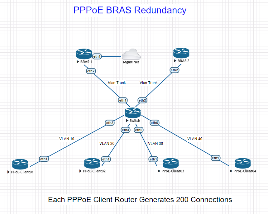
This LAB is intended to show the mechanism to provide HA fail-over between two AC’s, not the different types of transport from which we get client traffic to the AC. In this scenario, we are using a switch configured to define a single Vlan to the PPPoE-Client and trunk all Vlans to the AC. Note: in this LAB, AC’s are labelled BRAS-1 and BRAS-2.
I have decided to use Vlan 10 and 30 as primary for BRAS-1, Vlan 20 and 40 as primary for BRAS-2. Take note, while we decided to allocate primary traffic sources to each AC, we still trunk all available vlans to them. This is to ensure that if a network related event was to occur and knock BRAS-2 offline, after the session/idle timeouts expire on the client, the client will still be able to make a connection to BRAS-1.
PPPoE Packet Sequence:
To better understand what we are doing, here is the PPPoE sequence of events that occur:
- PADI – This is the discovery packet sent by the initiating client. Are there any access concentrators (AC) out there…
- PADO – The AC receives a discovery packet and responds with this message. Typically includes the MAC address of the AC, any defined service names and some other stuff.
- PADR – Client receives the offer and sends a request for connection to the AC
- PADS – AC confirms the request, builds the necessary session information, and confirms to client.
- PADT – This is a termination packet sent by either the AC or client. Tears down the established session.
The above is a very basic layout of the process, if you wish to understand more please look at the wiki page linked above.
When there is only one AC in play, the client has no choice who to connect to, obviously. However, when we introduce a second AC, and assuming we have not configured service-names or other identifying parameters, the client will choose the AC with the lowest MAC address in the offer packet. This means the connection will most likely always be too the same AC, even though both are responding with a PADO and the client receives them.
Solution:
Now that we have that out of the way, we can begin to understand how we achieve a HA design with load balancing. By using the PADO packet offset mechanism. Take a look now:
Image may be NSFW.
Clik here to view.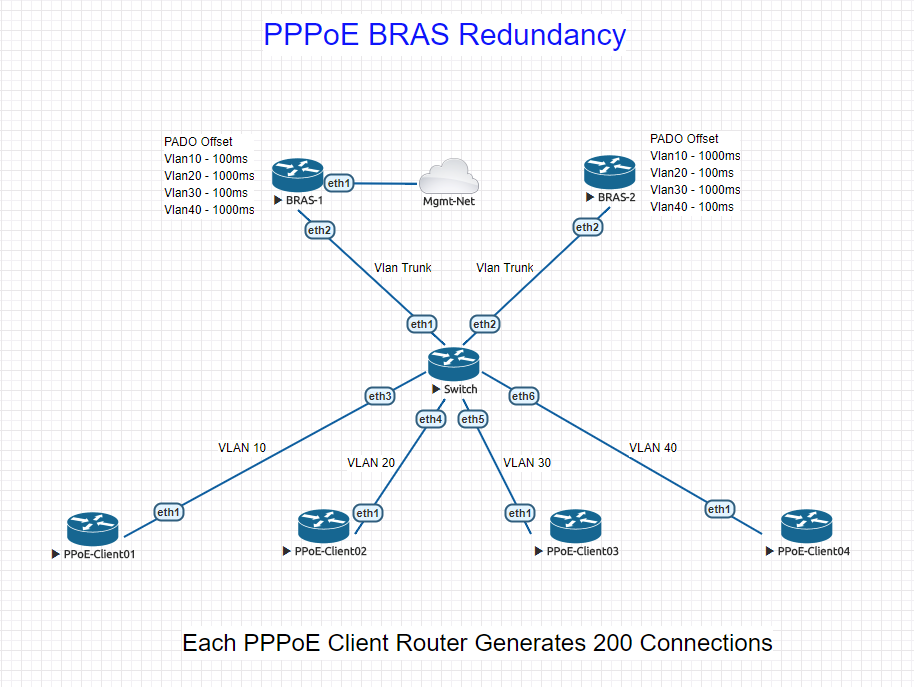
As you can see on the lab drawing, there is a defined PADO offset for each vlan on both BRAS devices. In MikroTik configuration, this looks as follows:
/interface pppoe-server server
add default-profile=PPPoE-Client01 disabled=no
interface=Vlan10-PPPoE-Client01 pado-delay=100 service-name=PPPoE-Client01
By offsetting the PADO (remember, it’s the offer sent back to the client) we can manipulate the clients into choosing which AC to send the request for session. Why? We are effectively delaying the PADO packet so that neither AC will respond at the same time. This allows the client to send its request to the first AC that it thinks is responding.
While I have used all MikroTik software in my LAB to create the test, Cisco and many other vendors have this option available. This will allow an ISP to scale large numbers of PPPoE sessions at the fraction of the cost of other well known vendors.
My LAB Setup:
- 2 Mikrotik CHR’s configured as the access concentrators, local authentication and IP assignments.
- 1 MikroTik CHR configured as a VLAN bridge, switch essentially.
- 4 MikroTik CHR’s configured as PPPoE Clients with a script to automatically create/delete 200 PPPoE connections on each.
- All CHR’s configured with one (1) CPU and 256M RAM on MikroTik free license level.
Assumptions:
Obviously there are many different factors that are assumed with this LAB. In the real world, such things as IP Addressing and authentication methods would need to be taken into account. For example, having the same IP pool present on more than one AC that handles client connections could very well cause issues, unless management of the CPE was not needed and the AC also performed NAT for the upstream connections. Though using a RADIUS billing/authentication system would solve this issue while making use of its own IP addressing pool. This would then more than likely require some IGP routing protocol to exist on the AC to tell the upstream nodes which address was present where, and when.
As I stated, this article is more to show it is possible and the mechanism in which to implement. All the other network minutia has to be considered individually…
Conclusion:
Using this mechanism allows for the use of multiple Access Concentrators to serve the same clients. There are many other ways to use the PADO offset in order to provide a scaleable, resilient authentication method when using PPPoE. Though, if you have a network with only one AC at the moment, following this approach will provide some extra piece of mind.
******EDIT – 4/24/2018*******
While this article does not go into how to build or use EVE-NG, you can download the EVE-NG topology and configuration files for the LAB here. All config files match the names in the LAB. There may be some cloud management changes you need to make to be able to winbox using ROMON etc. Username/Passwords on the CHR’s are default.
On the client PPPoE routers, there are two scripts that can be run:
To ramp the connections up.
/system script run add
To tear the connections down.
/system script run remove
Hopefully this helps people out.
*******************************
Here is a short video showing the connections ramping up on both AC’s.